(Joint authorship of "transresch Antriebssysteme Berlin GmbH" (Berlin, Germany) and PLUTON (Zaporizhzhia, Ukraine)
Authors – Ignatenko V. N., Kupets A., Mishchenko A.V., Ovsyaniker D. Y., Tsimbal P. P.
Phone number: (061) 220-48-11, (061) 220-48-40, (061) 220-48-27.
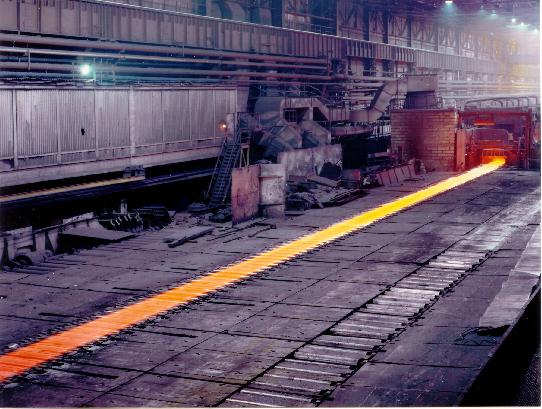
The article is dedicated to automatic AC electric drive and ACS of delivery table of continuous hot-rolling mill for web rolling at PJSC Zaporizhstal. Frequency converters of the rolling table electric drive and automatic system controlling the process of flat transportation are described here.
Introduction
While modernization of the continuous hot rolling mill for web rolling NTLS 1680, one of primary mills at PJSC Zaporizhstal, a question rose. This question was related to improvement of delivery table drives and development of ACS for rolling strip transportation from the last finishing mill to coiling machines, folding machines or flying shears.
Structurally the rolling table consists of 6 groups, with from 28 up to 36 rollers in each group, that are subdivided into even and odd subgroups. Further, it is planned to install from 48 up to 50 rollers in each group after replacement of mechanical equipment. Depending on control type 6 groups of the rolling table are divided into two sections. The first one includes the first and the second group. The second section includes the third through the sixth groups. Each roller is equipped with 2.5 kW driving asynchronous motor with squirrel-cage rotor. Rollers from the first through the fifth group are connected to motors via reduction gear with 1.4 gear-ratio. Rollers from the sixth group are connected directly. Some types of motors differ in characteristics with less than 10 % dispersion in the rated value, except the rated speed that equals 635 rpm at the synchronous speed of 750 rpm. Previously, rolling table motors were powered by rotary transformers (two transformers for each group) through individual circuit breakers. These transformers changed motors rotation speed and rolling strip transportation speed respectively due to change of output voltage and frequency.
Operation mode of rotary transformers as well as automatic circuit breakers position were monitored by the machine room operator according to panel-mounted pointer indicators. Operator directly monitored the flat and rollers, as well as operation of the rolling table. The transportation speed was set manually, separately for each section. Actual speed of transportation was out of monitoring. Such monitoring usually caused flat creases during transportation, especially when cutting several circuit breakers in one group of the rolling table. Besides, lifetime of rotary transformers has expired a long time ago, generators often failed, and it caused consequent standstill and substantial maintenance losses.
The need in the rolling table drive modernization with application of frequency converters (FC) and development of automatic controlling system was obvious.
The purpose of modernization
Modernization goals included:
- maximum automation of the rolling table electric drives control process;
- exclusion of rolled stock defects while transportation;
- providing manual and automatic rolling table control modes, combined and separate control of the rolling table groups and sections;
- providing automatic and manual setting modes of rolling strip transportation speed, option of individual speed setting for each group;
- providing possibility of the rolling table electric drive control from three operator positions and possibility of equipment modes monitoring for machine room operator;
- significant improvement of the electric drive operation dynamics for higher productivity and to avoid standstill;
- total automatic monitoring of operation of all ACS units and electric drive including data visualization and operation errors archiving;
- integration of rolling table control system into rolling mill ACS;
- reduced consumption of the electric power and peak current loads of power transformer during dynamic operation modes;
- excluding consumption of the reactive power by the rolling table electric drive.
This task "transresch Antriebssysteme Berlin GmbH" (Berlin, Germany) and PLUTON (Zaporizhzhia, Ukraine) had to solve on the working mill within a short time.
Electric drive
"transresch Antriebssysteme Berlin GmbH" (Berlin, Germany) manufactured and delivered frequency converters specially designed for rolling table motors operation control. Converters have all necessary features of the latest converting units:
- cabinet construction, prepared for use, with built-in power safety fuses, disconnector, input reactor, RFI filter, input sinusoidal filter;
- with an option of single-motor and multi-motor asynchronous electric drives;
- provide stable free of changeover motor, generator operation modes and regenerative braking mode;
- having sinusoidal input current and facilitating regulation of the power factor within the following range: from minus 0.8 to + 0.8;
- using Profibus DP serial interface for controlling and information interchange;
- highly dynamic, torque reversion less than in 2 ms, with valid characteristics in all 4 quadrants;
- providing total diagnostics of all systems, with emergency logging, emergency trace, with all necessary converter and motor protection systems.
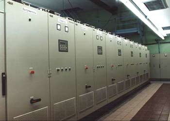
Structurally frequency converters consist of two one-sided maintenance cabinets. The power circuit and the control system are modular. Such structure is very convenient when setting, servicing, maintaining, identifying and recovering of malfunctions. IGBT modules were used when creating supplying and rotating converters; each converter is equipped with individual MPCS, having identical design and circuit, but different software. A fiber optic cable was used in circuits controlling IGBT modules. Its application provided high noise resistance and reliable operation.
There are three frequency converters operating motors of every rolling table group: two working converters for odd and even subgroups and a standby one. A standby converter is permanently connected to the system and can be enabled after simple switching of output circuits.
Automatic system controlling roll-table
Functions
The developed system was mainly intended for generation and distribution of signals of setting frequency converters speed in each group of run-out table, for run-out table sections operation during the flat transportation in different modes and for equipment state signaling.
Accirding to the actual problem control system should provide:
- continuous data interchange between PLC СS;
- gathering, processing and analysis of information concerning the run-out table and СS;
- generation of control actions;
- transmission of control actions (signals, commands) for execution;
- inspection of control actions execution;
- technological signaling;
- representation of necessary parameters and coefficients;
- online entering and changing of velocity parameters;
- online variation of system setup;
- control over technology compliance with necessary blocking and limiting;
- protection from incorrect actions of the staff, which may cause the emergency situation of run-out table and control system (CS);
- protection against unintentional alteration and data and software damage, as well as against unauthorized operation;
- setting up the CS without interruption of the engineering process, protection against accidental or faulty changes;
- control algorithms in different operation modes, including "speedup", "stop", "speed jam", "slow down" algorithms;
- diagnostics with place, kind and reason indication of rolling table and control system irregular functioning;
- acceptance acknowledgment of warning and emergency messages;
- system operation logging;
- registration and storage of information concerning pre-emergency condition of CS and operational FC ("breakdown trace");
- error protection while entering and processing of data, which provide necessary quality of CS functioning;
- absolute functioning when having only necessary data (lack of some data doesn't influence functioning if they are not engaged);
- HMI;
- unified time in the whole system.
System structure and hardware
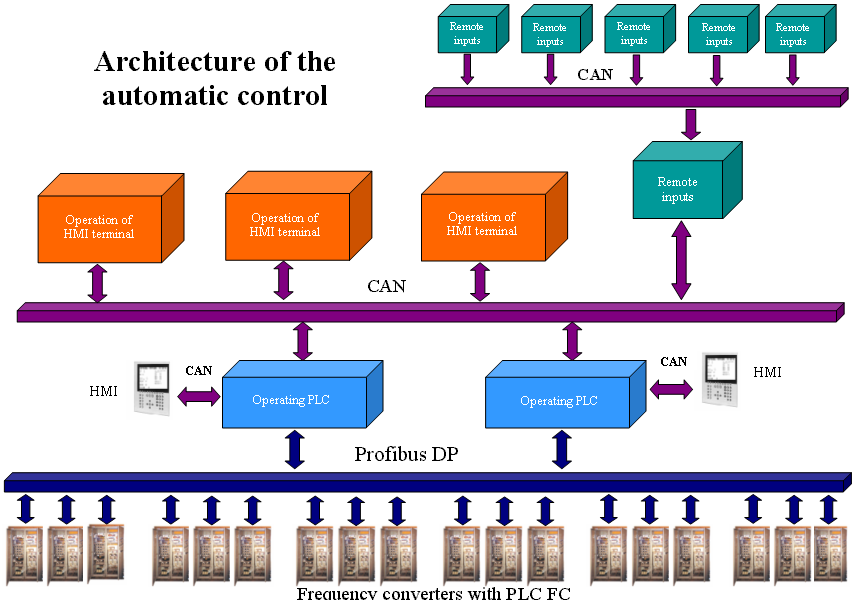
Drive operation is handled by controller parts of the control system and frequency converters (PLC CS and FC). Operation of drives of roll-table groups is parallel and independent, i.e. PLC CS generate control signals and interact with all working PLC FC simultaneously. PLC CS is based on B&R SYSTEM 2003 and 2005 controllers. PLC CS includes two control cabinets (CC), one of them is a stand-by CC, three control terminals (CT) and six cabinets with controllers for gathering remote inputs data (PLC RIO). Each CC is equipped with an operating controller (PLC) and a controller with display panel (PLC DP). Standby CC is always ready for action, it automatically changes mode from standby to operating and requires no auxiliary setups before working instead of primary CC.
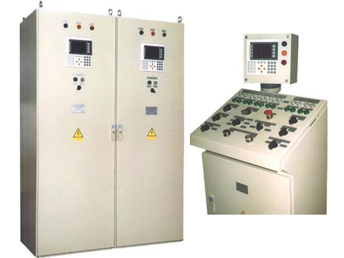
Three operator control terminals (CT) are distributed along the rolling mill. CT are located on control positions, scattered through 100-200 m one from another. Each control position provides a full-scale operation since every CT is equipped with PLC DP. Six PLC RIO are distributed along the roll-table, directly near cabinets with circuit breakers, which cut motors of roll-table groups. PLC RIO are scattered through 100-200 m. There are one "MASTER" and five "SLAVE" among those six PLC RIO and a CAN network connecting all 6 PLC RIO one with another.
Operating PLC located inside CC (one of them is "MASTER" for the network) and PLC FC are connected with Profibus DP, which is an industrial network. PLC FC are "SLAVE" (in all 18 (12+6) "SLAVE", however it can be increased up to 32). Operating PLC CC and three PLC DP of control positions are connected with CAN network. PLC RIO MASTER of remote inputs level is also connected to CAN. Besides, each operating PLC CC use an individual CAN to connect its PLC DP. So, each operating PLC CC belongs to Profibus DP network and two CAN networks. Also operating PLC can be connected with the system of rolling mill ACS level with Modbus network.
In all PLC CS consists of 26 full-scale PLC and 5 PLC receiving data from remote inputs. Such structure of connections resulted in increasing of reactivity of the system, i.e. time reduction of input parameters inquiry and generation of control action. In spite of huge quantity of PLC and complicated network structure the whole complex operates as a single reliable mechanism. Control position and control cabinet are equipped with PLC DP. It provided reliable system operation and enabled some service options, which systems with PC-compatible industrial computers have. For instance, being near some subsystem, one can observe engineering process, diagnose equipment or network, change values of different coefficients (if authorized), work with archives, while the engineering process continues.
Since control position is equipped with PLC DP, operations stuff can look through all necessary parameters of the engineering process. One can use "more/less" switch or keyboard to set the velocity level in online mode. Incorrect actions and emergency conditions activate the pilot light and immediately textual description of the situation appears. There are records and archives containing the entire work progress. Suppose, one of motors has broken down (or there is another reason for a circuit breaker to switch off) then it cause immediate signaling. One can see an explanatory statement in the screen of display panel, and identify broken motor in accordance with corresponding window. Controllers belonging to CC and three control terminals interact one with another. At the same time primary CC receive and process data, and then generate directing and other responding signals. Standby CC receives, represents and records input data. It doesn't transmit directing and responding signals via network. In case of need primary and standby CC exchange the functions: primary CC becomes standby one and vice versa. Removal of standby CC for fixing, updating, testing and so on won’t cause problems. It can be engaged again after this.
Three identical control terminals (one for each position) equipped with individual controller, display, signaling and operating facilities provide an option of roll-table operation from one of three operator positions. One of three CT operates in working mode, other two CT — in a standby mode. They display and record data. Control and operation is executed from the working terminal. At the same time all adjustments are stored in CC and remain valid after transfer of control to another CT. Facilities and limits of adjustment, which can me executed from CT are set in CC. At any time complete information concerning the operation of the whole complex can be transferred from CC to any CT on operator requirement. Abnormal operation, attempt of unauthorized action or mistakes of the staff immediately display and store in all three CT and both CC with corresponding time record.
Three CT, two CC, one PLC RIO "MASTER", connected with CAN network, cover 0.04 km2. Total length of network is more than 800 m.
Software tools
PLUTON used B&R Automation Studio 2.10 (AS) for software development. AS can be used for development of intellectual systems of gathering and processing of information.
AS is an integrated development framework that facilitates PLC programming using any of the following six programming languages: Basic, C, Instruction list, Ladder Diagramm, Sequential function chart, Structed text. The package includes powerful tools for developing and debugging programs (detection, localization and recovery of errors). AS provides partial loading and verification of programs and changing of some programs without correction of other programs.
We applied the "C" language for developing of the control system program (everyone knows its facilities and brevity). B&R Fieldbus Configurator was used for integration of operating PLC into Profibus DP network. The system had to be implemented into continuously working object — the roll-table was available for 15-20 minutes 1-2 times a day. That’s why there were special requirements for code written by us.
In some cases we developed models involving Borland C++Builder 5 for debugging of complicated algorithms. At first we debugged complicated algorithms using PC without B&R equipment, and then we involved PLUTON research and complex benches.
The software
Software provides all functions that control system imposes and facilitates the initiation of all necessary processes. Software provides accomplishment of all automatic functions in real time in all regulated modes of system functioning.
We complied with the following principles while developing software:
- functional sufficiency (completeness);
- reliability and validity (correspondence to given algorithm, control and filtering of input data, absence of faulty actions);
- modular structure and encapsulation (the software is subdivided into tasks, each task processes its data);
- multitasking (simultaneous running of several programs);
- hierarchy (different program priority);
- adaptability and flexibility (fast configuring and control algorithms restructuring);
- modifiability (facility of modification and expanding, modernizing, development and raising);
- serviceability and maintainability.
Structure and specific features of software
Entire PLC CS (only its controller part) can be logically divided into structure with following levels:
- level of operating PLC. On this level the following set of operations is executed: operating of eighteen PLC FC due to signals, received from PLC CT, unauthorized engage blocking, transfer of data to CT. The system is equipped with two operating controllers, each of them can be used as primary or standby one;
- CT level: centralized operating of the whole roll-table can be executed from any of three CT;
- Human-machine interface level (HMI). Equipped with two PLC DP. Each PLC DP is connected with one operating PLC;
- remote inputs level.
The CS includes 26 full-scale PLC. Engaging all PLC is not necessary for full-scale operation. Unengaged at the moment in the EP equipment can be turned off for precaution, for instance, and then turned on again. The system will record it, but won’t be interrupted. Total number of signals used in the system is 696 (with 100 ms clock cycle). There are 473 quantized inputs, 83 quantized outputs, 3 analog inputs, 3 analog outputs, 79 digital inputs, 55 digital outputs among them. Since there was found an optimum distribution of functions between PLC CS while designing, we managed to pack all application software inside 4 AS projects. For instance, all three PLC of CT level are programmed with identical software, in spite of slight differences in operating functions and display windows. When the application software starts it adjusts to functioning in specific component of CS.Each project is divided into tasks. It increased modularity and simplified project maintenance.
All tasks have an optimized clock cycle. For instance, all operating algorithms of the system have a 100 ms clock cycle, and some displaying tasks – 500 ms clock cycle. We’d like to stress on set of service functions of the system for its equipment diagnosing. The maintenance staff has already appreciated these facilities. In addition to detailed diagnostics and visualization software considers the human element of operations staff involved in roll-table operation. For instance, one can use traditional switch or keyboard for online changing of the velocity. The system can be easily readjusted due to huge settings number, which can be changed by maintenance staff with the help of display panels. However the password is needed to enable new settings. While executing tasks in PLC, application software is handled by the operating system (OS). OS for considered PLC family is well adapted for its application in the sphere of automatic control. It is a state-determined multitask system which provide operation in strict real time mode.
It is difficult to give detailed characteristics of all peculiarities of developed application software within limits of the article. We just want to stress that we used following advantages of the multitasking system while developing the application software:
- deterministic multitasking;
- different classes of tasks;
- controllable cycle duration for every class of task;
- optimal loading of the processor;
- priority of classes of tasks;
- flexible system update;
- file for errors recording;
- single task verification.
Fundamental results
Complex, which includes FC and ACS of the electric drive of delivery table has been set in industrial operation on 1st of October 2002. Putting of FC and SAC into operation proved that engineering solutions, found during the system development were absolutely correct. Even minor experience of operation revealed that ACS provides a reliable control and has a simple and convenient interface. It provides operations and maintenance staff with complete information concerning the roll-table, facilitates necessary switching and system precautions in online mode. Application of described FC and ACS for the electric drive of delivery table decreased losses on maintenance of the electric drive, improved its reliability, efficiency and flexibility of operation.
During 7 months of operation there were no standstill, defects or other contingency caused by FC or ACS. Due to application of roll-table drive electrical energy consumption reduced by 30% (approximately by 50000 kW.h per month). Peak load of the power circuit reduced four times. Reactive component of the DT ED consumed power was completely excluded and partially reactive component of other consumers was compensated. The dynamics of DT ED operation improved 2.5 times. It can reduce or even exclude standstill during contingency.
Conclusion
Results of performed work show that integration of efforts, experience and technical potential of "transresch Antriebssysteme Berlin GmbH" (Berlin, Germany) and PLUTON (Zaporizhzhia, Ukraine) provide development of automatic electric drive and complex PCS in the shortest possible time and on the high technical level.
List of used abbreviations
- PLC — programmable logic controller
- HMI — human-machine interface
- FC — frequency converter
- PC — personal computer
- CS — control system
- PLC CS — controller part of the control system
- CC — control cabinet
- PLC RIO — cabinet with a controller receiving signals from remote inputs
- CT — control terminal
- PLC DP — programmable logic controller with display panel
- EP — engineering process
- CAMS — CAM system
- AS — B&R Automation Studio
- ED — electric drive
- DT — delivery table
- RTD — roll-table drive
- ACS — automated control system
- OS — operational system
- PCS — process control system